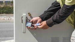
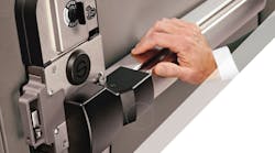
The Securitech three-point high-security locking system is ideal for retail applications with high value merchandise, such as cannabis stores, jewelry stores and high-end electronics stores. In fact, some predict that such businesses will be required to install these rugged locks by insurance carriers looking to reduce theft claim payouts.
It utilizes a lever that collapses these vertical rods. This is an unusual install because it’s on an inswing door. Normally the lock would be installed on an outswing door. Assembles can be ordered so that the internal components are inside the door, but this is a conversion kit.
This assembly includes the main mortise body and the upper portion. Everything pivots off of the top trigger device. Through-bolts go all the way into the frame and then a hinge pin locks down on the bottom, into the floor. The three points of contact basically turn this thing into a gigantic vault.
Now we’ll go over the step by step instructions on the installation for this particular application. Make sure that you first check all the instructions for your specific installation and that you have all the parts.
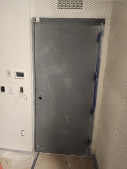
We start off with the blank door, shown in Photo 1, and we look at the instructions to get an idea where this thing has to be mounted. Depending on your application, the centerlines may differ. For this installation, we use the measurements that are required by the manufacturer.
Once you get your centerline, you can then make sure that you have the correct model number and that the model number is actually handed correctly. In Photo 2, you can see that yellow highlighted LH. Make sure you have the correct mortise body and the correct lock for the installation.
In Photo 3, we are dry fitting to make sure things look as they should to the eye. It gives you a chance to see any last minute changes without drilling into the door.
Photo 4 shows all the parts. I put all the parts out so we can make sure all the parts that are supposed to be in the package ARE actually in the package.
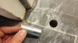
The first holes we are going to drill (Photo 5) are the self-tapping screws to hold the mortise body to the door (Photo 6). The next holes are the ones that attach the external trim to the internal portion of the case. It is held together by that extension nut (Photo 7). Here are both of them, top and bottom. The external trim goes on the outside. This extension nut threads onto that and other bolts thread in from the outside, holding the complete case together,
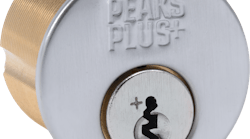
Photo 8 shows the exit trim with keys mounted and ready to go. Interchangeable cores would be a very good option. It would not be fun to take the lock apart to change the locks all the time.
Our handing today is very unusual, meaning it is on the inside; it is a pull instead of a push. Photo 9 shows the top bracket, which was incorrect when it was sent out. Photo 10 is from the next day. We had the correct bracket overnighted. You can see that it gives that little lever or that trigger a little bit of space because the silver portion is what triggers the black bolt to fire off into the top portion of the frame. Without the correct piece, you cannot do the installation. The gap allows the portion of the lock to hit and engage and fire off the bolt.
Photo 11 shows the carriage bolts or through bolts that go completely through the door. This plate and round heads of these carriage bolts are all that you’ll see from the outside.
Photo 12 shows the external portion of the case put back onto the mortise case, and we’re doing that so we can properly align the vertical linkage and make sure that it’s straight. You’ll want to get an accurate measurement from the bottom, where it goes into the mortise case, and transfer that to the top so that the vertical linkage is all perfectly straight. Make sure that your measurements are accurate all the way up and down. (Photo 13)
Once you have it measured out, it’s time to start drilling the through bolts. I like to start with the through-bolts and I prefer to mark them out with a marker and pre-drill them and then actually mount the through-bolts. (Photo 14)
Once you have that bracket in place and the first piece of the vertical linkage mounting put together, the next portion is shown in Photo 15. These pieces come stuck together with a piece of plastic. You break them apart. There is a specific right and left side and the only reason they’re bound together is for shipping purposes.
In Photo 16, you can see the through-bolts on that mounting bracket behind the block. The screws do not hold the black pieces in place; they hold the metal pieces in place. These just literally float on here (Photo 17) until you put the coverplate on. I found that a very small dab of superglue will help hold this in place but not hold it there permanently. It will keep everything from moving around while you are assembling and if you need to, it could be easily broken so that you could move or service anything. That’s just a little tip that I found to be useful.
This particular spacer plate (Photo 18) is very important. This goes in a very specific location. Because we have the external coverplate that slides over it, it has to have a gap to slide into. In Photo 19, I’ve got a thick shim, a thin shim and the spacing shim. I then set all these into place and I begin to mark the holes out with my Sharpie (Photo 20).
Next, I’ll predrill the through-bolts down at the bottom, and with a smaller drill bit, I’ll predrill the self-tapping screws. I chose to mount this in this location to cover up the joining portion where the two pieces of metal come together. (Photo 21)
Photo 22 shows what it looks like from the outside with the carriage bolts in place. Again, nothing but a flat plate and a metal rounded head is visible so you cannot undo the screws. The through-bolts come all the way through to the inside, and we’ll put the supportive strap on over that. Photos 23 and 24 show the lock washers and the nuts fully seated and the self-tapping screw fully seated. You can begin to see the gap and how this cover plate slides over and covers up the screw holes, making a nice looking finish. It slides right into the little gap and that is why it is important to put that particular spacer plate in the specific direction. Photo 25 shows it fully assembled. Photo 26 is the bottom support, also fully assembled. It looks very nice and clean, stainless steel.
Now we begin mounting the top bracket (Photo 27) or the top catch for the top bolt. This is going to be an external mount, so we’re simply going to bolt this U-channel piece of steel to the top. I’m a big proponent of marking your holes out. It’s easier to predrill everything and then put things together, as opposed to trying to drill through the plate where things could get scratched. If you need some sort of a spacer plate, you need to do a very good alignment and make sure that the bolt is free floating in that void securely.
In Photo 28, we have the top vertical linkage and we’re now going to attach it to the mortise body. The vertical linkage comes out of the mortise body and engages with that ladder-style system on the top. That is selectable. Make sure you check your measurements and clearances before setting that particular measurement.
Photo 29 shows two tabs or two locations that go into the ladder bar. Photo 30 is the clip that holds this in place. It goes through both tabs and it locks and holds everything in position. Should there be any need for expansion or contraction later due to wear and tear, it is adjustable. We add the bottom one as well. Now this mortise body unit is fully connected with the vertical linkage, making everything work and function together.
Again, everything is external, so this big bolt from the mortise body (Photo 31) has to catch onto something. We have to mount this catch onto the frame. In photo 32, I’m marking the holes out with my drill bit (obviously my Sharpie will not fit through there.) Make sure you have plenty of clearance on both sides and that the bolt floats freely and has some room to move around and sag. Doors are always going to sag; if you can account for sagging, that helps.
Measuring tape is going to give me a location of where I can drill from the outside in, if you do not have extra-long drill bits. (I finally decided to go get some longer drill bits out of the truck)
Photo 32 shows the carriage bolts. These bolt all the way through the entire frame and that locking block on the inside, to make this opening a rock-solid unit.
In Photo 32, the unit is almost completed. All we are missing is the external cover plate on the outside. We’ve got all the spacers and everything in place, ready to go. Photo 33 shows the coverplate installed and the internal trim finally installed.
There is a square spindle with a spring that goes into the handle and that drives the mortise body. Photo 34 shows the door completely sealed and put together. Notice the wire mesh shim all the way around the drywall. This is a high security room.
In Photo 35, you can see that the bottom pin drives into the floor. We needed to create the floor pocket for it. What I do is close the door, have that mounting bracket in place, and then I actually draw around the pin. Then I come back with a diamond hole saw and cut out the bottom strike pin pocket. Photo xx shows it shut, locked and fully bolted down. We bolted the floor strike down and used JB Weld epoxy or SteelStik rather than a very liquid type of epoxy. The liquid type could possibly fill that container where the pin goes and cause some major problems.
Photo 36 shows the completed external portion of the door. This will have electronic access, so we have wire running through the hinge and through the door, but that is another company’s job. Now we have a reinforced unit that is ready to go and fully functional.
To watch the video, scan the QR code or go to www.youtube.com/watch?v=q5bjU4pHhvo
Wayne Winton is the owner of Tri-County Locksmith Services, located in Glenwood Springs, Colorado. Check out WaynesLockshop.com and lockreference.com for more information.
