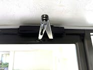
The new Corbin Russwin DC6000 Series door closers are direct replacements for the DC2000 Series closers. These new door closers incorporate double O-rings, a new spring tube design, arms, captured valves and self-drilling screws. The DC 6000 Series are ANSI A156.4, Grade 1, multi-sized, fully adjustable 1-6 (full and half sizes) door closers that are UL/ULC/UL10c listed for fire and cycle requirements. The DC6000 Series door closers conform to Barrier Free Code Compliance and the Americans with Disabilities Act (ADA).
I was invited to the installation of a Corbin Russwin DC6210-M54 door closer onto a 3’0” x 9’0” Labeled Curries hollow metal door. At the time this 1-3/4” thick door was manufactured, 12-gauge reinforcement was built into the door to accommodate a door closer. This was a new installation as a door closer was never installed onto this out-swinging exterior door. The decision was made to install the door closer using the parallel arm with offset angle bracket mounting.
(View all article images on a new page)
The Corbin Russwin DC6210 is a parallel arm mounting door closer that enables the closer to be mounted onto the interior side of an out-swinging door by using an offset angle mounting bracket. This bracket enables the arm to be mounted facing outward. The term parallel arm mounting indicates the arm is positioned almost parallel to the face of the door.
Sex nuts and bolts were used to secure the closer to the door.
IMPORTANT: Before installing or retrofitting a door closer, make sure the door closes properly. Make any necessary repair to the door, jamb, hinges/pivots, and/or floor prior to installing the new closer.
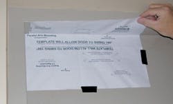
Step 1. Position the template onto the door and jamb to locate the mounting holes for the QUIK INSTALL™ mounting bracket. It is important to make sure the closer body is mounted level to the header.
Step 2. Mark the four drill points for the QUIK INSTALL mounting bracket.
Step 3. Drill the four mounting holes. Begin with a 9/64” pilot hole and finish with a 3/8” opening through the door for mounting the sex nuts and bolts.
Step 4. Mount the QUIK INSTALL mounting bracket using the included sex nuts and bolts. Position the narrow opening of the mounting bracket towards the hinge edge of the door. The DC6210 can only be mounted onto the bracket in one direction.
Step 5. Position the template onto the header to locate the mounting holes for the offset angle mounting bracket.
Step 6. Mark the four drill points for the bracket.
Step 7. Drill the four pilot holes through the steel header.
NOTE: The header was concrete filled. This required special drill bits to drill through the concrete once the hole was drilled through the steel header.
Step 8. Mark the length of the included self drilling screws on the carbide drill bit to make sure enough material is removed to permit these self drillers to screw in completely.
Step 9. Install the offset angle bracket mounting using the four included self-drilling screws.
Step 10. Mount the closer body onto the bracket and secure using the two 1/4-20 x 1/2” oval head machine screws (OHMS).
Step 11. Rotate the spindle 45 degrees to preload the closer using a crescent wrench. Maintain the spindle in this position and attach the main arm onto the upper spindle end.
Step 12. Mount the arm rod onto the offset angle bracket.
Step 13. Attach the 5/16” hex head screw with washer onto the top of the spindle to secure the main arm onto the closer.
Step 14. Slide the arm loop onto the arm rod and adjust the position. Install the 7/16” hex head screw and washer onto the arm loop to set the overall length of the arm loop/arm rod.
For maximum closing force, position the connection between the main arm and the arm loop at three inches from the face of the door. For normal operation, move the arm loop/arm rod parallel to the face of the door.
Open the door and allow it to close several times to test the operation of the door closer. The Corbin Russwin DC6210 door closer is set at a factory default of approximately a size three closer.
Adjusting The Closer
For the purpose of this installation, the spring power was sufficient to close the door. The following procedure is followed to adjust the closer. Start with the closing (sweep) valve. The closing valve controls the speed that the door closes from the fully open position to approximately 20 degrees. A decision was made that the closing speed should be approximately six to seven seconds. Turning the closing valve clockwise slows the closing speed. Turning the closing valve counterclockwise increases the closing speed.
The latching valve controls the speed that the door closes and latches. The latch range was adjusted to about two to three seconds. Turning the latching valve clockwise slows the latching speed. Turning the latching valve counterclockwise increases the latching speed.
There are two backcheck adjustments, the backcheck location valve and the backcheck intensity valve. The backcheck location valve, an on-off valve sets the location of the backcheck. In the off position, the backcheck starts at an earlier position. In the on position, the door can be opened further. For our installation, the backcheck location valve in the off position permits the door to be opened from 65 to 70 degrees. With the valve open, the door can be opened from 95 to 100 degrees. For this installation, the floor stop on the landing is at approximately 95 degrees.
The backcheck intensity adjustment limits opening force by slowing down the intensity at which the door can be opened. Turning the backcheck intensity valve counterclockwise reduces the amount of backcheck. Turning the backcheck clockwise increases the amount of backcheck. Too much backcheck can cause a sudden stop. The proper adjustment is a smooth slowing of the door.
IMPORTANT: The backcheck must never be used in place of a door stop. Over time, using the backcheck as a door stop will result in the closer mounting screws becoming loose and door closer mal-functioning.
Test the operation of the door closer.
Write the date of installation onto the body of the door closer using a permanent marker. This way, if the closer malfunctions, you will know whether the unit is still under the warranty.
Once all of the adjustments have been made and the door closes properly, install the cover onto the closer using two 6-32 x1/4” Phillips head screws.
Corbin Russwin DC6200 Series door closers are available in painted or plated finishes. There are a number of available arm configurations including hold open and heavy duty. For high vandalism applications, these door closers are available with security screws.
WARRANTY:
Ten year limited warrantyTIME TO INSTALL:
30 minutes to one hour. The time required varies depending upon the composition of the door and jamb.
For more information, contact your local locksmith wholesaler or Corbin Russwin, 1902 Airport Road, Monroe, NC 28110. Telephone: 800-543-3658. Fax: 800-447-6714. Web site: www.corbin-russwin.com.


