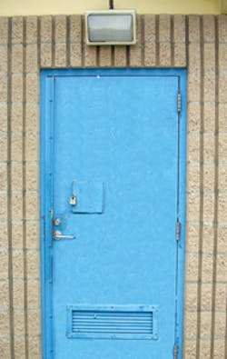
I was invited to the retrofit of the door lock hardware for a standalone employee bathroom in vandal-prone area where there were no public restrooms. The existing lock hardware was a keyed, storeroom function mortise lock with lever handles. An LCN 4041 surface-mount door closer completed the installation. The mortise lock and strike had seen better days as there was evidence of repeated prying on the edge of the door, lock and jamb. As an earlier attempted fix, a thick length of angle iron was bolted onto the exterior lock edge of the door.
The solution was to install a rim exit device onto the interior side of the door and a stainless steel push/pull handle onto the exterior. To reinforce the 18-gauge door, a stainless steel kick plate was located between the exit device and the door. To control access, a rim cylinder was creatively mounted into the lower portion of the push/pull plate.
The hardware installed includes a Detex Value Series Exit Device, Don-Jo Kick Plate, T-Strike and Scalp Filler Plates, BBW Push/Pull Plate and a Best Rim Cylinder. A complete shopping list can be found in the sidebar article.
Installing a rim exit device relocates the latch away from the edge of the door. This improves the security, making unauthorized access much more difficult. The stainless steel push/pull plate and kick plate provided additional protection to the rim cylinder and the exit device.
The Detex Value Series Exit Device was ordered to accommodate a 36-inch wide door. To check for clearance, the device with end cap attached was positioned on the interior side of the closed door. There was no need for modification as the device fit the opening.
The locksmiths decided to use #1/4-20 drill (TEK) screws in place of the supplied #1/4-20 machine screws to install the hardware. #1/4-20 screws have 20 threads per inch. Most common drill screws have sheet metal threads, spaced wide apart. Sheet metal screw threads do not have the same holding power and should not be used to install hardware onto metal doors and jambs.
IMPORTANT: Before installing any lock hardware, be sure to test the operation of the hinges and closer. Be certain they operate and are able to the close and latch the door. Adjust the door closer to insure optimum closing.
Step 1. Install the T-Strike filler plate. The lip can be used as a gauge.
Step 2. Remove the existing lock hardware and angle iron.
Step 3. Position the plastic template and the mounting plate onto the interior side of the closed door.
Step 4. Slide the template with mounting plate up and down to determine the location for the exit device. Because this is a retrofit, there were holes in the door that could weaken the installation. In addition, there was reinforcing built into the door. The mounting plate was aligned at a height that ensured a proper installation.
Step 5. Mark the locations for the mounting plate.
Step 6. Install the mounting plate using a #1/4-20 x 1" TEK screw.
Step 7. Use the level and position the mounting plate on the door.
Step 8. Mark the top and bottom of the mounting plate on the door edge. These two marks will be used to locate the kick plate.
Step 9. Maintain the mounting plate in position and use a center punch to mark the location for the rim cylinder tailpiece. Slide the mounting plate out of the way.
Step 10. Position the rim cylinder template using the tailpiece location as the guide. Mark the location of the center and the two screw holes. The center mark will be used to locate the opening for the rim cylinder in the exterior side of the door, as well as the opening to be drilled through the kick plate on the interior side of the door.
The rim cylinder template was created by the locksmith to simplify this installation. To make a rim cylinder template, use the rim cylinder lock plate as a guide to draw the circles. Locate the center of the circles by drawing to lines that bisect at the center point. NOTE: Using the rim cylinder's lock plate ensures the hole locations are correct as hole locations can vary by lock manufacturers.
Step 11. Drill a pilot hole through the rim cylinder center mark from the interior side of the door through the exterior side of the door. Make sure the drill bit is level and straight. Look through the mortised opening in the edge of the door to check for level. For this installation, a #7 drill bit was used for the pilot. This hole must be level and straight as the interconnection between the trim and exit device determine the ease of operation.
Step 12. Draw a horizontal line from the hole on the exterior side of the door to the edge. Draw a vertical line down from the hole. These lines will be used to locate the rim cylinder and the push/pull handle on the exterior of the door.
Step 13. Remove the mounting plate.
Step 14. Position the kick plate onto the interior side of the door, making sure the plate aligns with the upper and lower mounting plate marks. Position the kick plate in the center of the door so the edges of the plate are centered in the jamb.
Step 15. Use one flange head TEK screw to attach the kick plate onto the interior side of the door.
Step 16. Place the level on top of the kick plate to level the plate.
Step 17. Install the remaining 11 flange head screws.
Step 18. From the exterior side of the door, drill the rim cylinder center pilot hole through the kick plate.
Step 19. Use a 1-3/16" diameter hole saw to drill out an opening in the kick plate, providing access to the door face. Drill through the kick plate only. DO NOT drill through the door. Cutting out only the kick plate allows the rim cylinder screws to be flush with the top of the kick plate. This enables the exit device's mounting plate to be mounted flush.
Step 20. Draw a vertical centerline at the base of the push/pull handle.
Step 21. Place the Push/Pull Handle onto the exterior side of the door. Align the center of the handle with the vertical centerline on the door. Position the handle with the horizontal line, making sure there is sufficient space for the rim cylinder.
Step 22. Level the push/pull handle.
Step 23. Use one flange head TEK screw to attach the push/pull handle onto the exterior side of the door.
Step 24. Place a level on top of the push/pull handle to level the handle, making sure the handle's centerline aligns with the door's centerline.
Step 25. Install the remaining five flange head screws.
Step 26. From the interior side of the door, drill the rim cylinder center pilot hole through the push/pull handle.
Step 27. Use a 1-3/16" diameter hole saw to drill through the push/pull plate and the exterior face of the door. The rim cylinder will mount into the door through this opening.
Step 28. Drill the two pilot holes for the rim cylinder screws and the pilot hole for the tailpiece as indicated by the template.
Step 29. Use a step drill to enlarge the holes to accommodate the screws and the tailpiece.
Step 30. Mount the rim cylinder using the escutcheon from the mortise lock trim as the spacer. The mortise lock trim was stainless steel and would spin if rotated.
Step 31. Place the mounting plate onto the interior side of the door using the tailpiece to gauge the location.
Step 32. Use a level to position the mounting plate vertically. Make sure the tailpiece is located in the center of the hole.
Step 33. Mark the location for the upper mounting plate hole.
Step 34. Drill a hole through the kick plate using a number seven drill bit. The drill bit should enter the mounting hole previously drilled for determining the locations for the rim cylinder.
Step 35. Slide the rim cylinder tailpiece through the butterfly cam on the mounting plate while placing the mounting plate onto the door. Use a #1/4-20 x 1" Tek screw and lock washer to attach the mounting plate.
Step 36. Level the mounting plate while making sure the tailpiece will rotate smoothly.
Step 37. Install the second #1/4-20 x 1" Tek screw and lock washer.
Step 38. Use a grinder to remove the portion of the tailpiece that extends beyond the butterfly cam. Test the operation of the rim cylinder.
Step 39. Install the Scalp Filler Plate onto the edge of the door.
Step 40. Depress the push pad and install the rim device onto the mounting plate.
Step 41. Slide the end cap bracket into the rear of the rail.
Step 42. Level the rim device and secure the end cap bracket using three #1/4-20 x 1" TEK screws. Test the operation of the rim cylinder and rim device.
Step 43. Fasten the device to the mounting plate using the two #1/4-20 x 1" TEK screws. Test the operation of the rim cylinder and rim device.
Step 44. Slide the filler plate subassembly onto the extrusion. For this application, there would be no dogging capability.
Step 45. Mount the end cap and secure using the two #1/4-20 x 1" machine screws.
Step 46. Use the strike as the template to locate the three mounting holes.
NOTE: The jamb was concrete filled. To drill the mounting holes, a #7 pilot hole was first drilled just through the metal jamb. Then a #25 drill bit was used to enlarge the opening to accommodate the #1/4-20 x 1" Tek screw. Once the hole size was correct, a 3/16" diameter masonry bit was used to remove the concrete. Drill out the concrete around the opening as the TEK screw will thread into the jamb metal for attachment. Avoid drilling into concrete using a high speed steel drill bit. Touching the concrete will immediately dull the drill bit.
Step 47. Once the three holes have been drilled, install the Tek screws. Test the operation of the rim device. If necessary, adjust the position of the strike.
Step 48. Install the case cover using the four #6-32 x 3/8" Phillips head screws. Test the operation of the rim device.
Step 49. Install the core into the rim cylinder housing. Test the operation of the rim device.
Step 50. Install the two #6-32 x 3/8" Phillips head screws in the base of the end cap. These two screws stop the end cap from being removed when the door is closed.
To keep the Value Series exit device in optimum working order, basic maintenance, including lubricating the latching bolt and dead latch using lithium grease, is recommended annually or as required.
This installation required thinking in two different directions. In addition to controlling access, consideration was required on how to combat vandalism. Installing a higher security lockset with exposed levers would not necessarily provide a long-range answer. Instead, by installing an exit device, the latch mechanism was moved away from the door edge, making it more difficult for unauthorized individuals to gain access. As the handle is not part of the lock mechanism, vandalizing the handle will not gain or restrict access. This may eliminate some of the temptation. In addition, the hardware on the exterior of the door is now stainless steel, which should have a longer operational life.
SHOPPING LIST
The following is a shopping list for the exit device, push/pull and kick plates, filler plates, and TEK screws installed for this article. Most, if not all, of these products can be purchased from your local locksmith wholesaler. If the products are not available, manufacturers' addresses, telephone, fax numbers, and web sites are included.
BBW 4" x 16" stainless steel Push/Pull Plate, Part number 1001-3-630.
Builder's Brass Works part of TRIMCO/BBW/Triangle Brass Manufacturing Co.), 3528 Emery Street, Los Angeles, CA 90023. Telephone: 323-262-4191. Fax: 800-637-8746. Web site: www.trimcobbw.com.
Detex Value Series V4001 x LD x BP2 x 626 x 99 x 36 Exit Device.
Detex Corp., 302 Detex Drive, New Braunfels, TX 78130. Telephone: 830-729-2900. Fax: 830-620-6711. Web site: www.detex.com.
Don-Jo Kick Plate, stainless steel, 10" by 34" and .050" thick.
The T-Strike and Scalp Filler Plates are available as a kit, part number FPK-86.
Don-Jo Manufacturing, 70 Pratts Junction Road, Sterling MA 01564. Telephone: 978-422-3377. Fax: 978-422-3467. Web site: www.don-jo.com.
Best Rim Cylinder, Part number 1E72-52-RP-626.
Best Access Systems, 6161 East 75th St., Indianapolis, IN 46250. Telephone: 317-849-2250. Fax: 317-806-3276. Web site: www.bestaccess.com.
TEK #1/4-20 x 1" drill screws.
If your local locksmith wholesaler does not stock them, consider purchasing them from a commercial hardware supplier such as Grainger.


