Door Security Solutions of Southern California, the manufacturer's representative group for the ASSA ABLOY companies, and Dugmore and Duncan, Corona, Calif., branch, are in the process of creating a hands-on training center. Locksmiths will be given the opportunity to install, wire, and service lock hardware on six frame-mounted doors and a number of working displays. I was given a preview of the facility, which provided the opportunity for this article on installing an electrified SARGENT exit device.
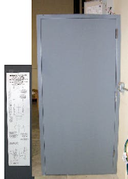
For this article, a SARGENT 56-8813 ETL Electrified Exit Device with trim was installed onto a Curries 707S hollow metal three-foot by seven-foot door with frame. To control access, a SARGENT 4293 Wall Prox was installed onto the frame. A 24 volt DC regulated power supply was used for this application. To wire the electrified exit device, a "QC" Concealed Circuit Hinge, part number TA2714 4.5 x 4.5 26D QC4, was installed. A door retrofit harness with four-pin connectors completed the installation.
The SARGENT 56-8813 is an electrified rim exit device operating in as Fail-Secure. When energized, the push rail and the latch bolt retract, unlocking the door. The exit device will remain unlocked until power is interrupted or de-energized. When power is removed, the latch bolt and the push rail extend placing the exit device in the locked condition.
For the exterior side of the door, the SARGENT ET Lever Trim was installed. The ET Lever Trim is manufactured of solid brass and is vandal-resistant. The ET Trim can lock or unlock the exit device from the outside using the key. When unlocked, the lever operates the exit device retracting the latch bolt. When locked, the ETL Trim lever is rigid.
To wire the exit device through the door and frame, SARGENT ElectroLynx standardized wiring and connector products were used. A Quick Connect Concealed Circuit Hinge with 4-pin connectors was installed at the center. The "QC" Concealed Circuit Hinge, part number TA2714 4.5 x 4.5 26D QC4, is equipped with four 28-gauge stranded conductors and a four pin female on each end. These UL Listed ball-bearing hinges have the conductors colored differently to assist in wiring the system. The electrical rating of the hinge is 1 amp per circuit @ 24 volts AC or DC. A 4-pin door retrofit harness connected the exit device to the hinge connector. The ElectroLynx connectors are designed to attach in one direction only.
A SARGENT 4293 Wall Prox was installed onto the frame. The SARGENT 4293 is designed to control access for a single opening. The 4293 Wall Prox can control up to 2,000 users with proximity cards and/or user codes. This indoor/outdoor controller has two relays: the main relay for the lock and an auxiliary relay for an alarm shunt, or for door monitoring. The face of the 4293 has a 12-button telephone style keypad, integrated HID proximity reader, and three LEDs. An audit trail keeps records of the last two thousand events. To gain full functionality of the 4293 Wall Prox, the SARGENT SofLink Plus™ access control PC software and the SofLink PDP PDA software are required.
For this new installation, the SARGENT 56-8813 ETL Electrified Exit Device was ordered to accommodate a Curries 707S hollow metal three-foot by seven-foot door with frame. Important: Order the exit device to the size being installed, as the rails of these electrified devices can not be modified in the field.
NOTE: Before installing any electronic or mechanical device onto a labeled door, contact the local authority having jurisdiction.
Step 1. Locate the template onto the interior side of the door with the chassis centerline at 41 inches above the finished floor.
Step 2. Mark the location of the four chassis mounting screw openings, the two trim thru bolt openings, and the opening for the rim cylinder and tailpiece from the ET Trim.
Step 3. Drill and tap four 10-24 holes to accommodate the chassis mounting screws.
Step 4. Drill two 11/32" diameter holes for thru bolting the ET Control to the chassis.
Step 5. Drill a 7/8" diameter hole through the door. Enlarge the outside diameter of the hole to 1-1/4" to accommodate the ET Trim.
Step 6. Mount the chassis onto the interior side of the door using the four flat head machine screws. Just snug the screws until the ET Trim and the rail are installed.
Step 7. Mount the ET Trim onto the exterior side of the door using the two 1/4"-20 x 2-3/8" Phillips flat head machine screws through the two center holes in the chassis.
Step 8. Depress the lift arm and slide the rail assembly onto the chassis.
Step 9. Attach the rail assembly onto the chassis using the two #8 Truss head machine screws.
Step 10. Locate the opening for the power at the end of the rail.
Step 11. Drill a 7/8" diameter opening to accommodate the ElectroLynx four-pin receptacle.
Step 12. Run the wiring from the interior side of the door through the Quick Connect Concealed Circuit Hinge.
Step 13. Slide the mounting plate into the end of the rail assembly.
Step 14. Use a lever to position the rail assembly.
Step 15. Drill and tap two #10-24 openings using the mounting plate as a guide.
Step 16. Install the two #10-24 x 3/4" Phillips round head machine screws. Test the mechanical operation of the exit device and the trim.
Step 17. Install the chassis cover and the end cap cover using the #8-32 Phillips head machine screws.
Step 18. Locate the position for the strike.
Step 19. Drill and tap two #10-24 openings using the strike as a guide.
Step 20. Install the strike using the two #10-24 x 3/4" Phillips head machine screws. Be sure to place one star washer per screw beneath the strike. Adjust as necessary to insure the exit device latches when the door closes.
The next step is to complete the wiring from the power supply to the 4293 to the electrified exit device. The negative wire is run from the power supply to the exit device. From this wire, a second wire is run to the negative for the keypad. The positive wire is run from the power supply to the positive for the keypad. From this wire, a second wire is run to the "C" for the keypad. A positive wire exits the keypad "NC" that connects to the exit device. See basic wiring diagram.
Power the exit device and test the operation. The default keypad code is 1-2-3-4. The default opening time for the SARGENT 4293 is five seconds. Read the instruction manual for the Wall Prox and program the device to accommodate the needs of the end-user.
Remember: Always change the default code.
SARGENT offers a variety of electrical products including power supplies and key switches.
For more information, contact your local locksmith wholesaler or SARGENT Lock Company, 100 Sargent Drive, New Haven, CT 06511. Telephone: 800-727-5477. Fax: 888-863-5054. Website: www.sargentlock.com.


