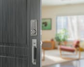
Schlage has introduced the CO Series, a platform of electronic locks that operate as standalone access control systems. These offline locks are ANSI/BHMA 156.25 Grade 1 and UL 294 listed for access control. They are available as cylindrical locks, mortise locks and exit device trim. Mechanical key override is standard and compatible with a variety of brands and types of cylinders. For the CO-Series mechanical key operation is required to reset the lock to the factory default.
Schlage CO Series locks are available in three models, the CO-100, CO-200 and CO-250 locks. The CO-100 is manually programmed using only the keypad and can store up to 500 3-6 digit PIN codes stored in the lock.
The CO-200 offers additional credential options that include keypad, proximity cards, magnetic stripe cards and dual credential capability including proximity card and keypad or magnetic stripe card and keypad. These locks can be manually programmed at the door. However, computer programming is necessary in order to take advantage of the full range of features.
The open architecture CO-200 platform can be operated using Schlage or third party access control management software. Depending upon the application, Schlage offers four levels of management software: SMS Express, Select, Premier, or Enterprise software. Using a Windows based personal computer, the access control management software program expands the capabilities of the CO-200 Series locks to include automatic unlocking and locking, holidays, time zones and audit trail including audit trail of mechanical override key operations.
Once a CO-200 lock is programmed via a computer, then manual programming is no longer possible and any existing keypad programming is erased. A computer programmed CO-200 lock can have up to 2,000 users and 2,000 audit trails.
The CO-250 offers two reader options magnetic stripe and magnetic stripe plus keypad reader. These computer programmable offline locks store user rights on the card. A computer programmed CO-250 lock can have an unlimited number of users and up to 4,000 audit trails. The CO-250 Series locks are programmed using the SMS Select, Premier, or Enterprise software, as well as third party access control management software.
Transferring data to and from the Schlage CO-200 and CO-250 locks from the management software running on a personal computer requires the Schlage Handheld Device (HHD) operating Schlage Utility Software (SUS). This same handheld device can capture diagnostic information about the lock such as battery and firmware level, as well as change configurations in the lock such as the magnetic reader track and audible feedback.
CO-200 and CO-250 locks are equipped with a USB port at the base of the outside lock assembly. The USB port serves to transfer the data from the HHD to the lock or retrieve audits from the lock to the HHD.
Schlage CO Series offline locks are specifically designed to take the place of legacy Schlage electromechanical locks. The CO-100 lock is designed to replace the Cobra and the Pro Series locks. The CO-200 Series locks are designed to replace the King Cobra 2 and the CM Series locks. The CO-250 lock is designed to replace the CL locks.
For those who have experience programming these legacy Schlage electronic locks at the keypad, the commands are basically the same for the keypad-equipped CO Series locks.
Schlage CO Series locks’ handing options are LH/RHR or RH/LHR, and are field configurable. The hand of the lock can be identified by the position of the lever catch. This spring loaded button that secures the lever to the lockset is always located on the same side as the latch bolt. To reverse the handing, the outside spring cage assembly must be rotated 180 degrees.
The cover must be removed from the baseplate in order to gain access and reverse the lock’s handing. For configurations with proximity or magnetic stripe readers, the credential reader is a separate integrated component that is removed along with the cover. On keypad only models, like the one reviewed for this article, the keypad credential is integrated with the base-plate.
Note on CO-200 and 250 Series Locks: Before removing the six or eight mounting screws (depending on credential reader option), the USB plug must be unplugged from the slot.
For this article, after removing the mounting screws from the CO-200 lock, slide the cover off of the baseplate. Note: Be careful removing the center screw on the rear left side. There is a Mylar pull tab in the slot adjacent to this screw. The pull tab keeps the lithium battery from contacting the electronics, ensuring the battery will be at “new” charge once the lock is installed. This pull tab is located in different locations for the proximity and magnetic stripe readers.
IMPORTANT: When installing a CO-200 or 250 series lock, be sure to pull out the Mylar pull tab to power the real time clock when the four AA battery pack is low or disconnected.
Once the cover has been removed from the baseplate, remove the two screws securing the spring cage. To change the handing, rotate the spring cage 180 degrees. The stamped area containing the word “LATCH” and an arrow will point in the opposite direction.
Reinstall the spring cage using the two screws, and the cover using the mounting screws. Note: The keypad-equipped lock used for this article required that a few of the buttons had to be individually aligned within cover slots before the cover would fit flush onto the baseplate. Use the eraser end of a pencil to reposition the buttons. Once the lock has the proper handing, it is ready to be installed.
For this article, we will install the Schlage CO-200 Keypad Cylindrical Lockset with privacy button onto a provided mount. The mount has been prepped for the installation of this CO lock. In addition to the five crossbore and edge bore lock mounting openings, two holes had to be drilled for the Door Position Switch (DPS).
The DPS tells the lock when the door is closed and when the door is open. The Door Position Switch is required only for privacy function equipped CO-Series locks. The classroom/storeroom and office functions do not require a Door Position Switch.
The privacy function allows a user to secure the door in such a state that normal access credentials cannot gain ingress. When the privacy function is activated, access can only be gained using a mechanical override key or a “Pass Through Credential.” This state is automatically cancelled when the interior push button is pressed a second time or the door is opened.
CO Series cylindrical locks use a modular variation for the retractor. The retractor mechanism is no longer a built-in component of the outside lock assembly; it is a separate component that is first installed onto the end of the latchbolt mechanism after it has been installed into the door edge. Once in place, a cover plate is screwed into place to keep the retractor in position.
Install the keyed outside lever prior to installing the outside lock assembly onto the exterior side of the door. The lock is aligned by using a straight slot screwdriver to rotate the cam into position. Once the cam is in position, the lock cylinder equipped exterior lever is installed. Make sure the lock cylinder retracts the latchbolt when rotated counterclockwise for a LHR installation.
Because the lock is handed, the outside lock assembly spindle hub must be aligned before installing onto the door. The two triangles must first be aligned. The spindle is then slid into the hub.
Once aligned, the outside lock assembly can be mounted after the two standoffs are screwed into the two top mounting holes. A 5/16” open-end wrench is used to tighten the standoffs.
Note: Schlage includes a plastic grommet that is installed onto the crossbore hole on the interior face of the door to protect the ribbon cable from being cut and exposing the wires.
To secure the outside lock assembly onto the door, an inside alignment plate is installed using through bolt screws into the outside lock assembly. Two mounting screws attach the alignment plate to the inside face of the door.
The inside lever and spring cage are then screwed into this plate. To operate the lock mechanism, there is a spindle that extends from the retractor mechanism, a spring and a die cast hub that slides into the inside lever assembly. This hub must be positioned with the two tabs vertical in order to position the lever horizontal. The retractor hub has different teeth to accommodate the spindle in order to position the hub correctly. Check to be certain the inside lever retracts the latchbolt when rotated clockwise or counterclockwise.
The next step is to install the inside escutcheon onto the inside face of the door using the two supplied screws. Once attached, run the DPS (if installed) wiring and the ribbon cable into the escutcheon. Make the three connections, the ribbon cable, DPS wiring and connect the battery holder wires. Once attached, properly position the excess wire and secure the battery holder using the provided strap and two screws.
Secure the cover onto the escutcheon. Test the mechanical operation of the lock. The next series of steps are to program the lock.
The CO-200 and 250 Series locks can be used in Construction Access Mode that allows all of the locks to be first manually programmed for construction access without the need to utilize the HHD. Even if construction mode is utilized, the locks can be reprogrammed for the end users’ specific applications.
One minor issue occurred during the installation of the CO lock. There was an initial problem getting the HHD to recognize that it was connected to the lock. We discovered that one of the batteries had come loose from the holder and while the lock could be manually programmed and operated, the voltage drop was enough to prevent the HHD from linking with the CO lock. Re-installing the battery solved the issue and the HHD connected to the CO lock. Note: When troubleshooting, always check the batteries first.
Manual programming the CO-200 at the lock includes single or dual credential programming with normal use, toggle, freeze and pass-through. The PIN can be a three- to six-digit code.
The Schlage button has two bicolor LEDs, one on the left and one on the right. All locks have a default programming code of 97531*. All locks have a default normal use code of 13579#. The default programming codes are removed once the user creates unique manual programming and enters normal use credentials or by programming the lock using management software.
To reset the CO Series lock to factory defaults:
Insert the mechanical override key into the lock cylinder.
Press and hold the Schlage button until the lock beeps twice and the button emits two green blinks.
Release the Schlage button.
Rotate the key within ten seconds and continue to hold the key until the lock beeps twice and the button emits two green blinks.
The Schlage button will emit a green light for one second and a one second beep will sound confirming the lock has been reset to the factory default.
The CO lock battery life for the 4 AA batteries is up to two years or approximately 73,000 operations. Low battery warnings start to occur when approximately 500 operations are left in the battery life. If the main AA batteries are low, the left light flashes red and the right light flashes red for low lithium coin cell.
If the batteries completely discharge, then the mechanical key is used to gain access to replace the batteries. The CO lock is equipped with non-volatile memory to insure against loss of data.
The CO Series locks limited warranty is one year.
For additional information, contact your local locksmith distributor or Ingersoll Rand Security Technologies at 877-671-7011. Web Site: www.schlage.com. For access to technical documents and online training tools, visit www.schlage.com/support .


