Alarm Lock DL2800 Trilogy: Programming Standalone Locks Using Data Transfer Modules
Self-contained electromechanical access control comes in different configurations to satisfy the application. These locks are available as cylindrical and mortise locks, single or double-sided, and as exit device trim that operates as standalone locking devices. When selling standalone electromechanical locks, it is important to know what functionalities the end-user wants and needs in order to control access.
Depending upon the application, standalone locks can be used just to control access. For example, a base model provides each user with a P.I.N. that operates the keypad-equipped lock 24/7/365. Most battery operated commercial grade electromechanical locks have more than enough user codes to accommodate most small businesses. The disadvantage of the base model is that access can be gained at all times.
Date/time scheduling provides the end-user with the ability to restrict access to specific times and days, eliminating access during the hours or days a company is closed. With time and date scheduling, audit trail makes it possible for the end-user to know which credentials have successfully gained access and which credentials have attempted to gain access during times they are not authorized.
The type of credential or multiple credentials enables the end-user to further restrict access by providing higher levels of security. In addition to P.I.N. operated keypads, battery operated locks are available with a magnetic stripe, proximity or Smartcard reader. The locks can be configured to require both a user code and a card to be presented in order to gain access. This dual credential requirement eliminates persons gaining unauthorized access by sharing a P.I.N.
Base models of electromechanical locks are available as standalone, battery operated units that are programmed at the door. Programming a lock at the door is fine for basic and limited operation such as an interior door where a limited number of users have access. The more features an electromechanical lock has, the more programming required to configure the lock.
The next level of standalone locks can be programmed using a laptop computer or data transfer mechanism. This makes programming much easier by having the ability to program each lock by downloading and uploading the information into the lock. The actual programming is accomplished using a computer. Electromechanical locks that operate on a Local Area Network can be programmed directly from the computer, being connected either by an Ethernet cable or wirelessly using a hub or gateway.
Although the new full featured standalone battery operated locks are equipped with network capability, the best lock for the specific application is not always the newest. For a small access control system incorporating two or three locks, a system can provide the controlled access wanted by the end-user using a computer and data transfer modules or a laptop computer to upload and download the programming instructions and the audit trail. The financial resources of the end-user must also be considered when selling an access control system.
For this article, we will discuss programming of battery-operated locks that are programmed using a computer and data transfer mechanism, specifically the Alarm Lock DL2800 Audit Trail Pushbutton Lock and the AL-DTMIII Data Transfer Module. The Alarm Lock DL2800 battery operated, standalone lock was chosen for several reasons including the Grade one, clutch equipped cylindrical lock, 200 user codes (3-6 digits), 1000-event audit trail with a real time clock for time/date stamp scheduling. The weather-resistant DL2800 has a 12-button, telephone style keypad. There is an entry allowance of 5-15 second and a temporary keypad lockout adjustable from two to nine unsuccessful entry attempts. Lockout time is adjustable up to 60 seconds. The five AA batteries provide 80,000 cycles, typical. For this article, we used the DL-Windows operating software version is 4.1.96, available free on the Alarm Lock web site.
For our installation, two doors will be equipped with the DL2800 cylindrical locks. They will be on the front door and the rear door. The Alarm Lock DL2800 installs into a modified standard ANSI A115 door prep, having additional through-bolt holes.
Before installing the locks, it is important to determine the users, their codes and their hierarchy. For this installation, the president determined who would be a user, the level and the time/date scheduling. Access and will be as follows. Three people will have access through the front door and seven people will have access through the rear door. Front door access will be for the company manager, assistant manager and the president. The president and company manager have access 24/7/365. The assistant manager and trusted crew will have access from 7:30 am to 9:30 p.m. Monday through Friday.
Access through the rear door will be for the company manager, assistant manager, cleaning crew and “trusted” employees. The president, company manager and assistant manager will have access 24/7/365. The cleaning crew will have access 24/7, no weekends or holidays. The employees will have access from one half hour before their shift during working hours only.
The one-time entry service code will be used by contract personnel or service providers as the need arises.
As shown in our chart, The Alarm Lock DL2800 locks have the following hierarchy of users: Master, Manager, Supervisor, Basic User and One-Time Entry service code.
The president will have the Master Code. The company manager will have Manager Code. The assistant manager will have the Supervisor Codes. The cleaning crew and employees will have Basic User Codes.
To program the user codes and the time/date schedules, Alarm Lock DL-Windows software is installed onto an IBM compatible computer equipped with a serial port or USB port. Laptop computers can be directly connected to the DL2800 or programming can be transferred using the AL-DTMII Data Transfer Module (DTMIII). For this article, we will use simplify the programming of each lock by using the DTMIII.
Once the DL-Windows software has been loaded onto the computer, opening the program will bring up a window as the starting point for all of the operations to program the locks, functions and users. To begin programming, right-click anywhere on the white vertical bar in order to bring up a pop-up and highlight new account. Type in a name for the installation. For this article, we will name it AL article. Then you have to create new lock profiles, one for each lock.
A lock profile contains the information necessary for a specific lock to operate including the user codes that will have access, the programmable features for each lock, and time zones and schedules permitting the user codes to gain access. Profiles are created for every Alarm Lock DL2800 lock in the access control system. The lock profile includes the description of the lock and the lock type. For this article, the description will be Front Door and Back Door. The lock model type is the DL2800.
Important: We will complete the front door lock profile as a template and then clone this for the back door lock.
The first window to bring up is the Global Users Account Name. Click on the Add Administrative Users button. This window is a database of the users, a place for their codes and the other functions including choosing the lock and the data transfer module (299). It contains the Group each user is in, who gains access and the credential required for access. Once the accept button has been pressed, any changes made in the future will be included.
Important: Always change the six-digit Master Code to a new code.
The Alarm Lock DL2800 allows individuals to be loaded one at a time or using an Excel spread sheet load all of the users at one time. The DL2800 has capability to import an Excel CSV file. To use an Excel spreadsheet, have the company create an Excel CSV (Comma Separated Values) file, containing the first and last names of the persons who will have access. This eliminates the need to type in each name individually into the DL-Windows software to create the user database. The format for the import is listed under “Tools” on the software.
Once the names have been generated into the front door lock profile, the software can randomly generate the P.I.N. codes. This eliminates the need to enter each P.I.N. individually. In addition, the DL2800 user codes cannot be subsets of the Master Code. For example, if the Master Code is 1,2,3,4,5,6, the user codes cannot be 1,2,3 or 1,2,3,4.
To generate the codes, select the first name; press the shift key, scrolling down to the last name and click. This highlights all of the names. Right click on the highlighted area and select generate selected new codes. Choose the code length (4-6) and all of the names will have randomly selected codes.
The next step is to create the time zones and schedules that restrict access for the users. For this installation there are users that have 24/7/365 access, users that have 24/7 access no weekends or holidays, and users that have access from 7:30 a.m. to 9:30 p.m. Monday through Friday. Some users will have access to the front and rear doors, some to either the front door or the rear door.
For this small installation, we will setup the time zones and the schedules the same for both locks as the president is not certain that specific employees will either be restricted to the front or rear door. For many installations, time zones and schedules can be lock specific. Having the three work schedules in each lock eliminates the need to program something in later.
Begin by clicking the icon Schedule. The Schedule-Time Zone appears. Type in the start time 7:30 a.m. and the stop time 9:30 p.m. Click enable for Monday through Friday. Right click on the different boxes for the short cut to setting the hours and days.
The next step is to create a user group for this schedule. In the Description, screen type in “Day Shift.”. Make it Group 1 in the User or Group ID. In the Event screen click, and then click the drop down to Enable Group to appear. In the Time Zone screen, click and click the dropdown to 1, for Time zone 1. This will give those users placed into Time Zone Group 1 will have access only from 7:30 a.m. to 9:30 p.m., Monday through Friday.
This schedule must be modified to prohibit access during holidays, as there is no need for a Group 1 user to gain access. Another time zone is created to disable the holiday dates. Disable schedules override enable schedules. Each holiday must be set each year as the holiday dates will not always be the same. Following the first year, only the dates will have to be changed at the beginning of the year.
Important: The Master, Manager and the Supervisor Codes can manually override the schedules and the time zones.
One more Group needs to be created for the 24/7 weekday access no holidays. The 24/7/365 is the default access so no changes are necessary. Do not fill in the Group information in the Global Users screen until the Back Door lock profile has been cloned.
To provide an additional layer of protection, the DL2800 can be programmed to activate the unlock command only when an authorized user enters his or her P.I.N. For example, by incorporating this feature, if there is a problem, earthquake, snow day, etc., the lock will not just unlock at the specific time.
In addition to controlling access by users, the DL2800 can be unlocked for a specific time, for example, a company that has a lunchroom. An Alarm Lock DL2800 can be programmed to automatically unlock at 11:30 a.m. and relock at 1:30 p.m., providing access during lunch.
The Programmable Features screen is lock specific. For the DL2800, some additional features under the Options tab include daylight savings time, remote release, lockout 2-9 number of times and the lock out time is up to 60 seconds. Keypad lockout is recorded onto the audit trail. This way someone will know if the lock is being manipulated.
Once the Front Door profile template has been completed, clone this template to create the Back Door lock profile. Not all of the users will have access to both the front and the back door locks. They will be programmed into the Front Door lock profile. Then by cloning the lock profile and creating the Back Door lock profile, there is no need to enter the names more than once. Should an employee gain additional access rights, the name will already be in both lock profiles. In addition, should the company want additional locks, having a clonable lock profile will save time.
Open the Global Users Account Name for the Front Door and select the user that belongs in each group. Do the same thing for the Global Users Account Name for the Back Door and select the users for each group. There will be users in both the Front and Back Door lock profiles that are not authorized to gain access.
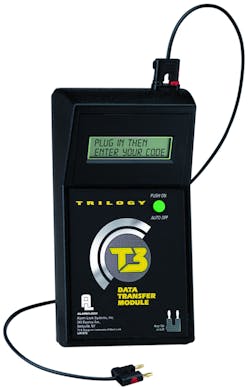
The next step is to use the Alarm Lock Data Transfer Module (DTMIII) to transfer the lock profiles containing the programming data from the computer to each of the DL2800 locks. The DTMIII can also upload the audit trail from the lock. The Data Transfer Module can store programming for up to 200 locks.
To connect the Data Transfer Module or the lock to a computer, a PCI cable is necessary. If the computer does not have a serial port or you do not want to worry about the connection, order the PCI cable with the USB to RS-232 connector part number AL-PCI2U. To be certain the DTMIII is properly connected and the computer is set to the COM port two, run the test to be certain. Open the software, click on the Tools and select COM Port Setup and Test. Press Test. Look for Loop Back Test with the COM port set to COM port 2.
Note: The advantage of the DTMIII over using a laptop computer to program the locks is the DTMIII allows someone to program each lock without having the ability to modify the programming.
Open the DTM window. The Front and Rear Doors should be listed. The Front Door is lock #1 and the Rear Door is lock #2. The DTM functions for each lock transfers the programming data for each lock separately from the computer to the DTM. The DTM must be in PC COM mode. Activate Front Door lock profile. Press Program DTM for Selected Locks button. Disconnect the DTMIII from the computer.
To prepare the Alarm Lock DL2800 for the DTMIII, enter the Master Code and the green LED will illuminate. Press the AL button. The green LED will flash every six seconds to indicate the programming mode.
To add the DTMIII to the lock, press AL 2 AL 299 AL 299 *. A double green and beep will indicate the DTM has been programmed to the lock. Wait two minutes or press and hold down any key to exit out of programming mode (red LED illuminates).
DTMIII is polarized; there is a black tab on the connector that indicates the negative wire. The black tab side of the connector slides into the black circle on the lock and the DTMIII. Attach the connector to the Front Door Lock. Once plugged in the first lock has to be identified. Set the DTMIII to Door Select mode. In Door Select Mode, the door number must be entered. This allows you to choose which lock will be programmed first. Enter door number, for our installation, the Front Door is #1 and the DTM code is 299. Upload the information to the lock. Note: The door select mode is only used upon initial setup, all subsequent visits the DTMIII is in “Lock Mode.”
After the Front Door data has been sent, repeat the procedure for the rear door and provide the user’s codes to the employees. Have all employees test their code to be certain they can gain access.
Once the locks have been in operation for a period of time, you can retrieve the data and the audit trail from each lock. The data and audit trail are retrieved separately.
The Alarm Lock DL2800 Audit Trail Pushbutton Locks provide the end-users with time scheduled access control with the ability to know who gained and were denied access at what date, day and time. This system can provide the features wanted and needed by small to medium sized companies.
Alarm Lock warrants the DL2800 and the DTMIII to be free from manufacturing defects in materials and workmanship for 24 months following the date of manufacture.
For more information on installing, the DL Windows software and programming the Alarm Lock DL2800, there are videos at Alarm Lock Web Site: http://www.alarmlock.com/video.html
DEFAULT DEFAULT
USER TYPE USER NUMBER GROUP ASSOCIATION PROGRAMMING LEVEL
Master Code 1 none M, 4, 3, 2, 1
Manager Codes 2-6 none 3, 2, 1
Supervisor 7 - 11 none 2, 1
Basic User Codes 12 - 50 none none
Basic User Codes Group 1 51 - 100 1 none
Basic User Codes Group 2 101 - 150 2 none
Basic User Codes Group 3 151 - 200 3 none
Initiate DTM (Non-Pass Code) 299 none none
Service Code 300 none none


