Tech Tips: Remote Control with the Camden LazerPoint
Radio controls were among the first wireless devices introduced into the security market. Wireless remotes were developed during World War II where they were used to detonate explosives.
After the war the technology migrated into the non-military markets. With the growing popularity of security systems and motorized garage door operators, wireless panic buttons and garage remotes became a popular add-on accessory.
Installing and servicing garage door operators was one of my earliest sidelines when I was subcontracting for locksmiths. Garage door operators involved wiring and batteries, and many old school locksmiths didn’t want to become involved.
Garage door operators also were mechanical, with chain drives and worm gear designs. As is the case with any specialty, the devil was in the details with the installation and servicing of these products. Changing a battery in a remote control was no challenge; however back then, most garage doors were made out of wood and were very heavy. Also because they were exposed to the weather and to damage from woman drivers, the doors required fine tuning and repair, and repairing those was a challenge and usually required more than one man.
I still have a tool I purchased way back then, a pair of very large water pump pliers which I really needed to install and remove the huge springs that were used to balance garage doors. With these pliers, I had the leverage and safety margin I needed to escape injury while working. Since a wood garage door could weigh hundreds of pounds, these springs were mandatory so the garage door could be opened either manually or with a motorized opener. The springs also provided a safety feature so the garage door would descend in a controlled and safe manner.
While most of the technology back then was hard-wired, wireless panic buttons and garage door openers were on the market.
At the time, the wireless technology was rather primitive in that its range of operation was relatively limited, and there was no such thing as “encryption” as we know it today. “Encoding” was used so transmitters could be matched to a receiver.
Many of the early wireless devices supported only 256 unique codes so it was not that unusual for garage doors to open mysteriously due to duplicate encoded transmitters or receivers in crowded residential neighborhoods. Criminal types would park in a neighborhood with a couple of remotes and try all the possible codes until a garage door opened. Then they would become burglars.
Of course the technology underwent rapid improvements so the technology could be used to improve security rather than jeopardize it.
These days there is a consistent market for garage door operators, gate operators, and automatic door operators, with low energy swinging door operators being the best fit for the typical locksmith.
Low energy door operators are a great upgrade, and wireless “Knowing Act” actuators are frequently used.
The code requires that low energy door operators be furnished with “Knowing Act” pushplates or other actuators and not be set up for automatic operation as high energy operators.
Approved low energy operators are designed to be self-contained and not require external safety devices, (again, unlike high energy operators which must be outfitted with safety accessories in order to meet code.)
Many installers will offer and install safety devices with low energy operators even though they are not required, because in many environments, the nature of the door usage or the demographics of the individuals likely to be using the door will warrant them.
It is important to note that wireless accessories are not suitable for use as or with safety accessories but are okayfor actuators.
All the requirements for low energy operators can be found in: BHMA A156.19-2013 POWER ASSIST and LOW ENERGY POWER OPERATED DOORS
The American Association of Automatic Door Manufacturers website (AAADM.com) is a best source for information on all aspect of the automatic door operator industry.
Camden Lazerpoint RF
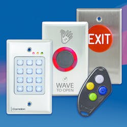
Camden Lazerpoint RF represents the latest in wireless automatic door control technology:
Lazerpoint RF is a completely new wireless solution for automatic door operators. The system introduces the many advantages of 915MHz. spread spectrum wireless technology to the automatic door market.
The Lazerpoint RF system encompasses the widest range of transmitters, receivers, activation devices and switch enclosures available today. Lazerpoint RF receivers use daughterboards so they also support 300MHz., 390MHz., and 433MHz. transmitters.
LAZERPOINT RF Features:
- Advanced 915MHz spread spectrum (broadband) wireless communications for outstanding range and performance.
- Multi-year battery life (using inexpensive 'AAA' alkaline batteries) and exclusive 'low battery','gas gauge' and 'stuck switch' audible alerts.
- New CM-RX90 advanced receiver, with one relay, features three relay modes (delay, non-delay & latching). It is ideal for vestible applications.
- RX-92 receiver model with two channels plus 6 operating modes; saves time and money by avoiding the cost of buying and installing additional components.
- Optional plug-in receiver modules provide compatibility with other RF frequencies.
- ‘PUSH AND LEARN' transmitter enrollment and signal strength indicators, makes LAZERPOINT RF™ the easiest system to install
- Camden product quality backed by a full 3 year replacement warranty
- 12 / 24V AC/DC operation means compatibility with every door operator.
- Convenient Terminal Strip means hassle free wiring (no dubious Marr connectors).
- 40 Code Memory accommodates larger installs.
- 1 – 30 second potentiometers are “user-friendly” (versus complicated dip switches).
- Instant ResponseTM Feature means even the briefest switch press insures reliable activation.
- 2 x dual function LED’s - Relay status, # of learned codes,
- Dual function LED bar graph – learned transmitter codes & Potentiometer VisualizerTM
- 1 or 2 Form C relays with 3 Amp contacts for dependable relay life.
- 33” LED Cable tool aids installer by duplicating on-board LED’s.
- Hand held Programmer (RFIQ) eases installation (coming soon)
Set-Up Instructions
The RX-92 has two relays, and three potentiometers with two 1–30 second adjustable Hold time (or delay-on-release) and a 1–15 second delay-on-activate for the second relay.
The 4-position dip switch selects from one of six different operating modes.
Dip switch #4 controls the display of LED 1 & LED 2. When set to OFF, it will display the operation of the associated relay(s). When set to ON, it will blink a count to indicate the received signal strength.
To facilitate set-up, set to OFF then select an operating mode.
Mode 1. Dual independent outputs Operates as a two channel receiver.
Mode 2. Also known as a switching network or make/break relay, use this mode with a door operator and lock.
Mode 3, Vestibule Sequencing. Select if you want to sequence two doors in both directions, using just one RX-92 receiver (requires two conductors to the second door)
Mode 4 Vestibule Sequencing. Select if you want to sequence two doors in both directions, using two RX-92’s and no wiring between operators
Mode 5, Latched Mode A. Access Control application. A transmitter signal learned into channel 1 will latch Relay 1. While relay 1 is latched, a transmitter learned into channel 2 will activate relay 2. When channel 1 is in the off state, the RX-92 will ignore channel 2 inputs.
Mode 6, Latched Mode B. Freight Door application. In this mode a transmitter will active relay 1 for an adjustable time, then latch relay 2. Relay 2 stays latched until another transmitter signal is received then drops out immediately.
Step 2 is learning the transmitter(s) to the receiver. The procedure for learning of transmitters is dependant on the specific operating mode but generally the procedure is as follows:
Press the PB1 (or PB2) button using a small blunt object such as a small blade screwdriver or similar. Within 10 seconds, press the switch connected to a TX-9 transmitter. You should then see the Green LED display light on the receiver to indicate the TX-9 has been received and learned. Repeat with any additional transmitters.
Pressing the learned transmitter again will signal the receiver that you are finished programming and LED’s 1 & 2 will flash, in an alternating sequence.
Pressing the transmitter a third time will activate the relay and corresponding LED, and also the device connected to the relay contacts.
There is no step #3, you are done programming!
If you wait longer than the 10 second period, the receiver will time out of Learn Mode and revert back to standby. The LED will then flash to indicate the number of transmitters learned into the receiver.
RX-92 TIMERS: The RX-92 has two relay hold timers (delay-on-release) of 1 – 30 seconds each (Pots 1 & 3). There is also a delay on-operate time for relay two (Pot #2). Walk-test and adjust the timers to suit.
Testing Signal Strength: To display signal strength FROM a TX-9 transmitter, set Dip switch #4 ON.
By setting Dip Switch #4 to ON, you can display the signal strength of the transmission from a TX-9 transmitter.
This enables the installer to confirm the transmitter is within the receiver’s range, and gives the installer a tool to perhaps optimize the receivers final location if nearby obstructions are preventing proper signal reception. Activate the transmitter, and observe the number of flashes of LED 1. Four or five flashes are ideal.
Deleting Transmitters: Pressing and holding either PB1 or PB2 for 8 seconds will delete all transmitters. The LED Array will flash rapidly for 4 seconds to indicate erasure of the codes.
Adding Daughterboards: A unique feature of Camden’s Lazerpoint RF is the ability to add one or two daughterboard’s, extending receiver compatibility to older technologies operating at other frequencies: 300 mHZ; 318 mHZ; 390 mHZ; 433 mHZ.
The ability to work with additional frequencies allows the user to utilize both hand-held transmitters as well as wall-switch-ready transmitters. There is a 40-code memory limit for each transmitter.
Using CM-RFCT Cable tool: A 33” long plug-in cable tool is available since the LEDs on the receiver may be difficult to see once it is installed.
The CM-RFCT Cable Tool plugs into the opening on the side of the receiver, and allows the installer to view LED’s mounted on the free end. Once the installation is complete unplug the cable tool, and re-use for the next installation.
Programming was very straightforward and intuitive.
For more information on the Camden Lazerpoint RF, contact your local locksmith distributor or visit www.camdencontrols.com.
Tim O'Leary
Tim O'Leary is a security consultant, trainer and technician who has also been writing articles on all areas of locksmithing & physical security for many years.


