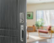
The Schlage AD-Series locks. This is a multi-card and PIN technology lock that also uses Wi-Fi and NFC credentials and readers. It’s a wireless lock. This lock is a great option for schools and retrofits because it can be used standalone and it can be used in a network.
will start our installation on a hollow metal door that’s prepped. You can see the cart we have with all of our tools in Photo 1.
We have quite a large project for this particular installation. Before we arrived, another worker used the jig to drill the door and prep the holes. Now it’s time to install the lock. (Photo 2)
Photo 3 shows the mortise body pocket. I’m using an impact driver with a No. 3 Phillips head bit. Be careful when using an impact driver. This can make your job easier, but make sure you don’t break or strip screws.
First, we insert the mortise body and put both screws in the mounting positions or tabs on the frame. Then, we put the coverplate on (Photo 4). Yes, you can put the cover plate on immediately, unlike most installations.
In Photo 5, we’re adding the door position sensor, and you can see that the door position sensor comes in from the side and the wires come through the center drilled hole. I like to twist the wires together to help feed them through the hole.
Next, we install the two studs that go through the actual mortise body. (Photo 6) You need to compare this and actually line the block up with the mortise body to see which two locations to use to mount these two studs. They can go in this position (Photo 7) or they can go in the opposite position, just depending on your handing and application.
Once we have those installed, we can then install the center square spindle with the beveled edge pointed out (Photo 8), and then align the two arrows on the spindle portion and the body of the lock for the outside, external, secure lock portion (Photo 9).
Feed the wire through the hole and line up the studs, inserting the exterior portion of the lock. In Photo 10, you can now see those two studs that we just put on the lock body, poking through the mortise body, along with the wire and the door position sensor.
We then install the anti-rotation plate. This plate has two screws with a tapered head. They’re the only tapered head screws that come in the packet. (Photo 11)
This is a metal door. If this was a wood door, these little screws could go right into the wood. However, on a metal door, you will have to pre-drill them. I found that a little self-tapping drill bit actually had the perfect sized hole for drilling these.
This helps to secure and reinforce the strength of the locks. It’s very important that this step not be skipped.
Now that we have the external portion of the lock installed, Photo 12 shows that this is an interchangeable core (IC) type of system. So, we’re going to put the core on last.
Next, for the internal portion, it’s easier to install the battery pack while the lock is in your hands as opposed to when it’s on the door. We put the battery pack in, put the cover strap over and installed the two screws shown in Photo 13. DO NOT CONNECT THE BATTERY.
Next, we install the spring and spindle. The spring goes in first and then the spindle goes in with the round portion going into the spring in the spindle hole location with the beveled portion of the spindle facing out. (Photo 14)
Once we have all this put together, we feed the door position wires and the connection wires from the external portion of the lock and feed the spindle into the spindle hole. These are the three things you must line up. (Photo 15)
This is where this particular version of the AD Series is a little bit different than the other versions. The way the wires actually come in through the lock is slightly different than some of the other versions, like the cylindrical leverset or the exit device version.
Photo 16 shows how twisting those wires together kind of helps feed it through wooden doors and metal doors so that those wires stay together. That’s a little timesaving tip.
Next, we install the major four mounting screws, two in the top and two in the bottom. These should be a 1/4 by 20 pan-head screw. They are the shorter ones. They are about an inch-and-a-half long, roughly. In photo 17, I’m pointing at the two screws that go in the bottom. These go into the mounting studs that go into the external portion of the lock.
Here is the entire lock, pretty much mounted and secured (Photo 18). You can begin testing to see if the handing is working; you can test the function of the lever and you can make sure that everything is working well at this point.
Now, two very long pan-head screws are actually going to go through the inside of the lock and connect to the external portion and that plastic piece on the outside of the lock.
Photo 19 shows both of these screws lined up. This is going into plastic, so I would highly recommend not using an impact driver. I would recommend lining them up by hand.
Here’s one of the screws that I’m guessing gets forgotten a lot (Photo 20). On a wood door, this would go right in. However, on a metal door, Allegion’s instructions do require this. If the door is metal, you need to pre-drill it and still install this screw. This is going to give the lock strength and rigidity, protecting it from coming loose, or possibly being torn off the door.
Next, we’ve got the door position sensor. You can see these two terminal blocks (Photo 21) and these two screws that say “DPS.” Prep the wires using a good pair of heavy-duty scissors. Trim the wires down so that you have a small portion designed to just make contact with the terminal block but do not have exposed bare wire. (Photo 22) These don’t have power running to them. However, when dealing with low voltage, this is always a good practice.
I loop the wires over (photo 23), run it in a little bit of a loop because I’m going to have to pack some more wires into here, and then run it over to the door position sensor. Nothing is being pinched or bound in any way, shape or form.
Next, I hook up the main plug. This plug has one simple line in it. Line that up with the adjacent line on the receiving portion of it, and simply plug in, do not force.
Photo 24 shows what I consider some kind of shielding material from Allegion. It’s basically like some aluminum foil with adhesive and I’m guessing it’s used to block RFID reading or scanners of some sort. You stick it on the door after the lock’s installed and you’re done.
Now, we put on the internal handle by sliding it over the handle post and clicking it into place. (Photo 25) This is one of the most important parts of the installation and needs the most care. The chip will come in a bag that says, “do not touch.” Make sure that you don’t have oily fingers. You can only touch this chip on the external portions or on the edges and right here in the center (Photo 26)
Notice how these two little plastic studs poke through (Photo 27) after this piece is seated in place. This is why I do this last, because it is one of the most important and delicate pieces of the installation process.
Now that all connections are made, you may plug in the battery pack.
Here’s another helpful tip. If you can bend or grip these wires, not pinching them, but just bend them a little bit so that they stay in place, it makes putting the bottom plate on just a little bit easier.
There’s one more machine pan-head screw for this bottom plate and two dark pan-head screws for the top (plastic, don’t use an impact driver) cover plate. That should suck that plastic piece down and cover the foil. (Photos 28 and 29)
Here we have a completed unit on a hollow metal door, inside (Photo 30) and outside (Photo 31).
For more information, check out Wayne'slockshop.com and lockreference.com.
Wayne Winton is the owner of Tri-County Locksmith Services, located in Glenwood Springs, Colorado.
Wayne Winton
Wayne Winton is the owner of Tri-County Locksmith Services, located in Glenwood Springs, Colorado.


