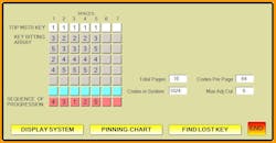
Building any master key system begins with a plan, often called a key bitting array (KBA). Terms used in this article may not conform to tightly held terms used by others but are meant to provide the simplest explanation of a complex subject. A key bitting array consists of the masterkey cuts to be used, the change key cuts and the order they are to be used in each space, and the sequence of progression (SOP). Chart 1 shows an example KB A with the top row showing the masterkey cuts- 11111, and the vertical rows showing the change key cuts to be used with each masterkey cut.
The bottom row shown in red shows the sequence of progression (SOP) for this master key system. SOP can be readily explained by studying the odometer in any vehicle. Vehicle odometers operate in units of 10. As the vehicle moves ahead, rotation "1" constantly changes from "0" through "9". Rotation "2" changes each time rotation "1" returns to the "0" position and starts to rotate again through the numbers. Uniformly, rotation "3" begins changing each time rotation "2” reaches "9", rotation "4" begins changing each time rotation "3" reaches "9" and rotation "5" changes each time rotation "4 reaches "9". SOP in a vehicle odometer can be thought of as 54321 where the right dial is constantly rotating and the left dial changes least often.
In the vehicle example, when the SOP number reaches "99999" no additional numbers are available without causing duplicate numbers. While master key numbering systems are generated in a similar fashion, there are usually approximately only four choices of numbers which can be used for rotation. In the chart one example, rotation "1" is in the third space. The master key cut is a "1" cut, so there are four available numbers which can be rotated- 2/3/4/5. Cut numbers from other columns do not change at this time. Key cuts 32223, 32323, 32423 & 32533 can be developed.
As with the vehicle odometer example, when those four key cut numbers have be used, Progression sequence "1" begins with the next column cut number "3" cut and rotation begins again using the next SOP rotation number ("2"). Key cuts of 32233, 32333, 32433 & 32533 can be developed.
When all five spaces have been rotated the final cut number would be 45552 according to the KBA and no further individual keys cuts are available. In a five pin master key system, using four change key cuts per space the total number of individual keys can be determined by the formula four (cuts) raised to the fifth power (spaces) equal 1024 total individual key cuts.
One last consideration is that most lock system will not allow a very deep cut next to a very shallow cut. Metal removed from the deep cut does not allow for metal to support the adjacent shallow cut. Each company has a set maximum adjacent cut value (MAC) which is usually "7". While the cut numbers will be part of the 1024 generated key cuts, usually approximately 10% of the 1024 key combination cannot be used because of MAC problems.
Each lock company has developed their own rules for which numbers can be used in a KBA chart. Most lock companies normally use depth increments of .015" from one cut depth to the next deepest cut. In order to set up a master key system, thin master pins are inserted on top of normal bottom pins to form two shearlines. 015" master pins are quite thin and may cause cylinders to malfunction in heavy use. In order to solve this problem, manufacturers suggest using thicker master pins of at least .030".
Another factor is that most lock manufacturers use a depth numbering system of 0-9 or 1-10 (ten increments). When using every other cut, master key systems are restricted to using cuts of 0/2/4/6/8 or 1/3/5/7/9. Since one of the key cuts is used for the top master key, four key cuts are available for the KBA key cut chart.
In addition to the 1024 change key cuts and single master key cuts, numerous other key cuts are available which can be used to lower level master keys. Lower lever master keys are developed by using a combination of top level master key cuts and cuts used by a group of change keys, In a five space master key system, horizontal master keys, vertical master keys, page master keys master keys which operate four pages of change keys can be developed.
Next refer to chart 2 and chart 3. These charts eliminate guesswork out of explanations above. Knowledgeable persons reading this article will notice that the top master key is cut "11111". This is not a real master key but rather the position in the example KBA. To use charts 2 & 3, develop your own KBA chart according to the rules for the lock system you are working with. Once you have inserted the desired master key cuts and change key cuts in each space, use the charts to determine the cuts to use for each change key. Numbers on pages 2 & 3 represent the positions on your developed KBA and not the actual cuts to use. Note that lower level master key cut positions on your KBA are also included for keying suites, apartment floors or other usage. Charts 2 &3 can be used multiple times whenever you are developing a master key system and regardless of the lock brand. These two charts can provide up to 256 individual change keys.
Finally, the sequence of rotation (SOP) cannot be changed. By inserting the "4" rotation in the first space and the "5" rotation in the last space large groups of keys can be set to a vestibule key system by leaving tumblers out of the middle three spaces. By using the first and last spaces, keys used in the vestibule system must be fully entered to operate.


