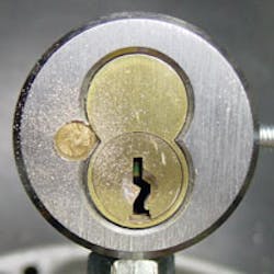
Unlike other commercial lock cylinders, figure-eight (small format) interchangeable cores require special removal techniques when keys are not available.
Interchangeable cores are normally removed by inserting the control key then turning the key clockwise about 15 degrees. When the rotation stops, the core is ready for removal by pulling it out of the cylinder, knob, lever, etc. Without a control key, the core is completely locked.
To rekey the lock or lock cylinder, the core must be removed. If the rekey job entails one lock, removal options are: to drill out the core or housing and replace it with a new one; or to pick the control level (shear line) of the core.
If rekey job consists of many locks using the same control key, the options are: to sacrifice one lock or lock cylinder to remove a core and decode the control key; to pick the control level of the core.
Picking Figure-Eight Interchangeable Cores
Figure-eight interchangeable cores can be difficult and time-consuming to pick, especially seven-pin cores. The locks have two different shear lines, the operating level that allows the lock to be accessed, and the control level that allows the core to be pulled from the lock.
If you don’t optimize your picking technique you will almost always pick the operating level. The primary reason why operating levels are easier to pick than control levels is the rotation of the operating level offers less resistance than the control level. Often control levels are difficult to rotate.
To facilitate consistent control-level picking, two techniques that can be used: applying pressure to the control lug or shell; or inhibiting the ability for the operating shear line to be picked.
Tension bars that grab the bottom portion of control shells can be made or purchased.
In Figure 2, the tension bar is inserted into the core and positioned until it drops into access holes at the bottom of the control shell. Unlike other tension bars, the handle is directed upward so that a better “bite” can be applied to the shell. When the tension bar is properly positioned, a greater amount of pressure is applied increasing the chances that the control level will be picked.
Another technique is to get pressure onto the control lug that protrudes on the left of the control shell. This is done by carefully drilling a small hole (3/32” drill bit) to the control lug. This requires checking the depth of the hole many times to make sure the hole is bored through the cylinder and barely touches the lug.
The hole is drilled on a slight angle so pressure can be applied to the lug with a pin extractor tool. Figure 3 shows the location of the hole.
Figure 4 reveals the picking technique. The pin extractor is firmly pushed up against the control lug. The extractor takes the place of the tension bar.
Once the core is removed, the hole on the face can be plugged with brass stock and filed smooth.
My personal picking technique is to inhibit the ability for the core to be picked to the operating level. Most of my time picking these cores relates to those that are master keyed and this technique is limited to master keyed cores. Fortunately most cores are master keyed.
Key blanks are milled across to what would be seven cuts. A key blank is needed for each keyway. The heads are also milled away (or cut off) to allow a pick to be inserted into the core. The milled key blank acts as an effective tension bar while inhibiting the core from being picked on the operating level.
What makes this occur is the fact that the largest bottom segment used in properly master keyed cores is a #7 segment. Pushing the altered key blank into the core can raise a few of the pin stacks to levels that bar the operating level while increasing the chance that at least one stack will directly align with the control shear line.
Insert the pick all the way into the core and work back-to-front, using more back-and-forth action versus up-and-down action.
Remember that picking these types of cores is always challenging and is not guaranteed. Picking is always the preferred method if time allows or if the core cannot be sacrificed. When time is an issue, drilling consistently offers a predictable time of completion.
Drilling to Preserve Pin stacks for Decoding
I prefer drilling to picking as it is a sure thing and the cost of core replacement is less than the cost of time to pick the core. Figure 6 features a “marking” tool I created by pinning a broken key blank and plug together. I simply insert the marking tool and score the core or cylinder. This gives me an exact drilling location.
Successful core drilling is like safe work, knowing where to drill and drilling clean holes, is essential. It is better to take your time and use a sharp drill versus brute force and over-sized holes.
In Figure 7 a “clean”, 1/4” hole is precisely drilled, removing all parts of the mortise cylinders face that normally secures the core. Once the face plate is penetrated it is easily pried out with a small screwdriver. Figure 8 is a close up of the finished hole. Figure 9 is a sectional view of all the pins in a typical seven-pin core.
It was necessary to “sacrifice” this mortise cylinder to keep the core intact. With the core in-hand, it can now be carefully disassembled and the control key decoded.
To decode the control key, the driver pins (in the sectional view those colored red) must be extracted in proper order then identified by determining pin lengths. The pin length can be compared to the manufacturer’s numbering designation.
The formula to determine the cut of a control key in a specific chamber is to take the value of the pin number designation and subtract it from 13. For instance, if a driver pin has been determined to be a #4 driver segment, subtract 4 from 13 to get 8. The cut of the control key in that chamber position will be 8.
This can be done by hand by carefully inserting a pin extractor at the bottom of a core and then carefully tapping it with a hammer holding pressure on that chamber with your finger. When you feel the retainer cap give, carefully elevate the pin stack and spring with the extractor.
The spring is the first component to be elevated out of the chamber. Directly following it is the driver pin to be decoded.
Although this technique requires a minimum of tools, it is a learned technique, requires practice, and is not as quick as specialized designed tools for the task. Figure 10 is an interchangeable decoding kit that streamlines the process.
To decode the heights of pins, use a dial caliper like the one shown in Figure 11.
With a key gauge, colored driver segments, and super glue, I created a visual gauge that allows me to quickly identify pins and relate them to control cuts without doing the math. I started by gluing a #4 segment across from the 9 hatch-mark and then worked up. When I visually identify the pin height I just glance up at the cut number. Figure 12 is an image of the altered key gauge.
Drilling When Decoding is not Necessary
Most of my work involves failed cores that no longer work with operating or control keys. This doesn’t mean that interchangeable cores prematurely wear out, but there are locations in which all commercial cores or cylinders will quickly wear out. This is a routine occurrence with me as many of the locks I service are opened hundreds of times each day.
The quick solution is to drill the core out and swap it.
There are two methods, my personal favorite, and that recommended by the manufacturer.
The first step regarding my personal favorite is to use the marking tool to score the drill location. This is shown in Figure 13.
Once scored, I insert a blank key to raise the pins and then use a 3/32” pilot hole to drill thru all chambers (see Figure 14).
Changing drill bits to a sharp #7, I increase the diameter of the hole (see Figure 15). The sharp hole creates a new shear line then the key blank is rotated to the removal position (see Figure 16).
The next method is the traditional means recommended by the manufacturer.
The first step is to locate where to drill. The manufacturer recommends between the “E” and the “S” but that won’t help you if the core does not have “BEST” stamped on it. I saved the face plate of a figure-eight core that was drilled out and use it as a locator for the proper drilling point. It is aligned with the core and an automatic punch is used to mark the location (see Figure 17). Once located the face plate is removed, use a #7 drill bit to bore a hole approximately ¼” deep (see Figure 18).
With the face plate fully penetrated (1/4” depth), use a narrow (but beefy) punch to pry the face plate off (see Figure 19). After the face plate is torn off, the control shell is exposed (see Figure 20).
The drilling with the #7 drill bit continues until all chambers have been pierced. As you drill runs through the chambers, it slightly binds revealing when the chamber is pierced. This is useful as it lets you know when to stop (see Figure 21).
The punch that was used to pry off the face plate is again used to force the control shell clockwise until it stops at the removal position (see Figure 22). The core is then pried out.
Brass shavings are removed from the back of the core then replacement core is inserted. The best method I have found to remove brass shavings is to blow them out using a long straw. Make sure and wear safety glasses before attempting this.


