Controlling access has become the new term for locking a door. This is because there are many different methods for controlling who is authorized to gain entry. There are the mechanical locks operated by keys, mechanical push button locks, electronic push button locks and the array of options and configurations for electromechanically securing a door.
Not any one lock mechanism will satisfy every application. The differences include the configuration of the opening, the location, the number of users that will need a method of access and the method of controlling access.
One method of controlling access that does not require a key, card, fob, computer, software or batteries is the mechanical push button lock. This lock does not have a keyway that can be “gunked” up with debris. The mechanical push button mechanism will operate in the more extreme temperatures. And only one P.I.N. code needs to be memorized.
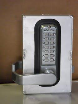
The Lockey 2835 is a medium duty, standalone mechanical lock equipped with lever handles. Lever handles are non-handed and can be installed to accommodate any door swing. According to Lockey, the levers meet Americans With Disabilities Act (ADA) requirements. The 2835 lock housings and lever handles are manufactured of zinc alloy; the push buttons and tumblers are manufactured of stainless steel. The internal body components of all Lockey push button locks are Teflon coated for added protection and longevity, eliminating the need for additional lubrication.
Model 2835 has 14 spring loaded push buttons, numbers 1-0 and letters X, Y, Z and C. The letter “C” is used to clear any previous buttons being pressed.
For this article, we will be discussing the Lockey 2835DC double combination version of this push button lock. The double combination (DC) lock has a keypad on the exterior and the interior sides of the door. Each lock assembly can be set to different codes for gaining access and egress.
Each keypad can be coded with the suggested three to six characters using the numbers 1-10 and the letters “X” and “Z”. For example, one of the provided lock assemblies’ codes is C1560. Remember: Always press the “C” button before entering a code to clear the chamber. This four-digit code can be entered in any order (for example, 1560, 5106 or 0165). However, a number or letter cannot be used more than once in a code.
When any code or no-code button is pressed, you will feel resistance part way. Once the button has been pressed, no resistance will be felt if the button is pressed again. The number is already seated into the code chamber and is not affected by being pressed again.
If an incorrect code is entered, the lever cannot be rotated. Press “C” to clear the chamber and start again. When the correct code has been entered, the lever can be rotated only once in either direction to retract the latch bolt.
The Lockey 2835DC has the passage function as a standard feature. Pressing the “Y” button after the operating code has been entered will place this lock assembly in passage mode. For this double combination lock, each keypad must be placed into passage mode for the lock to operate in passage mode. To reset the lock back to normal operation, press the letters “Y” and “C” on both lock assemblies.
When installed with the rubber escutcheon, the lock is 6-1/2” tall by 2-9/16” wide. Door prep requires two cross bore openings. The upper opening is 5/16” diameter for the upper mounting screw. The lower opening is a 1-7/16” diameter or for retrofit, the 2835DC can be installed into a 2-1/8” cross bore door prep. The lower opening is for the spindle, the latch bolt support pin and the lower mounting screw. The latch bolt requires a 7/8” diameter edge bore opening. The default backset for the 2835DC push button door lock is 2-3/8” backset. The backset required for the gate boxes available from Lockey is 2-3/8”. For commercial applications, the 2835DC lock can be ordered with an optional 2-3/4” backset latch bolt.
The Lockey 2835DC uses removable stainless steel tumblers to set the operating code. The blue tipped tumblers are the no-code tumblers. The red tipped ones are the code tumblers. Four code tumblers are pre-installed in each lock. Up to six provided code tumblers can be used in the combination chambers.
One blue or red tumbler is placed into the combination chamber directly beneath 1-0 and “X” and “Z” push buttons. Because the 2835DC lock has passage function, the “Y” combination chamber must be equipped with the non-color tumbler. The “C” combination chamber tumbler must never be removed.
Changing the Code
The lock assembly must be removed from the door.
Unscrew the four red anodized screws from the rear of the lock. Be careful, as the numbered plate is spring loaded as the springs place pressure on the tumblers.
Lift off the plate and set aside. The springs are attached to the bottom of the plate.
To remove the code or no-code tumblers necessary to change the code, press the “C” button and lift out the tumblers to be changed using the provided tweezers. With the “C” button pressed, insert the code and no-code tumbler to set the new code. Release the “C” button. The tumblers cannot be removed or installed if the “C” button is not depressed.
Once the combination has been changed, place the plate on the lock assembly and thread the four red anodized screws. Snug the screws. With the lock assembly in your hand, test the code several times. If the lever handle can rotate, the code is correct. Enter the code and press the letter “Y” button to see if the lock assembly goes into passage mode. Press the letters “Y” and “C” to exit passage mode. When satisfied with the operation, secure the four red anodized screws.
Install the lock assembly onto the door.
The 2835 lever handle lock with passage function is available in antique brass, bright brass, satin chrome, satin nickel, jet black, white, bright chrome, oil rubbed bronze and a saltwater resistant marine grade finish. Teflon coated finish that is resistant to saltwater corrosion.
Lockey offers tamper proof mounting screws for installing their locks. Contact Lockey for specifics.
The Lockey Web Site, http://lockeyusa.com, lists installers’ names, locations and telephone numbers. To be added to the list, email Lockey with your qualifications and contact information and request being added to the list.
Warranty: Limited lifetime warranty for locks manufactured after 2000. Requires dated proof of purchase.
Tools to install: Phillips screwdriver, drill motor 5/16” drill bit and 1-7/16” holesaw.
Door Prep: Two or three openings to accommodate the two mounting screws and the spindle
Time to Install: Approximately 20 to 30 minutes.
Important: Before installing any double sided lock, contact the local authority having jurisdiction (AHJ) to obtain authorization.


