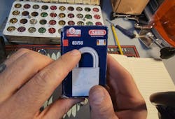
Today we are going to be rekeying the ABUS 83-5- Series padlock (Photo 1). On the packaging, you’ll see the OB number of 300 (Photo 2). This indicates that it will have a Schlage SC keyway, so that we can rekey it to match other locks that have a similar Schlage keyway, such as a deadbolt or lever lock.
To watch the installation, along with a bonus section showing more details about padlock operation, scan the QR code or go to https://www.youtube.com/watch?v=KhFJrQP0sWA.
We are going to follow the instructions, taken right from ABUS’ homepage (see sidebar). We will rekey the padlock to the key shown in Photo 3.
The first step is inserting the key and actually opening the padlock. Now if you have a brand new padlock, use the keys that come with it. You should have a zero-bitted key from the factory.
Photo 4 shows a Phillips head screw down in the bottom in the open side of the shackle. It will release the screw with the shackle open and the cylinder will begin to drop out, or come out of the bottom. It’s a good idea to have this hovering over your pinning mat or something soft so it doesn’t get scratched or damaged.
Photo 5 shows what the cylinder looks like when it comes out. You’ll notice that we have the cylinder in one hand and the lock housing in the other.
To rekey this lock, we have to push in the little detent (photo 6). You can either use your finder or a small screwdriver. It will rotate under the rest of the housing assembly, keeping it hidden and tucked out of the way, as seen in photo 7. This will allow us to see the pins coming out of the rekeying window.
Now we are going to decode our key. This key is going to decode to 1-1-7. If you do not have any of these LAB decoders (shown in Photo 8), I highly recommend them. They make rekeying keyways very, very convenient.
The second group of cuts are going to be a 3 and a 3. The total combination for this lock is 1-1-7-3-3.
In photo 9, we are beginning to insert the pins into ABUS’ patented rekey window. In photo 10, you can see the pins, all in alignment. Because of the way that I am holding the lock, they do all look like they are slightly too high. However, I can assure you that when you put pressure on the key and lift it up, they all drop down into their proper positions and at their proper heights, as seen in Photo 11.
You’ll notice that my lock has a different design for the sixth chamber. ABUS does not even list this on their website yet. However, there’s a sixth chamber that you can add to add an additional pin with a separate packing. We’ll talk about that later.
Photo 12 shows the Z-bar. It has a little black dot on one side. If you assemble the lock so that the Z-bar goes onto the cylinder, the black dot will go up. If you put it into the chamber like I’m doing in photo 13, the black dot will go down. You can see the Z-bar inserted and in place in photo 14.
According to ABUS, the Z-bar is a patented feature of the 83 Series. It is a small metal piece that enables a quick and easy change between key retaining and non-key retaining, all available in one single standard padlock.
With the key retaining function, the key remains in the lock and cannot be removed until the cylinder is locked. Once it’s locked, you can remove the key. Non-key retaining means that you can remove the key without it being locked, allowing it to be dummy locked. You have both options.
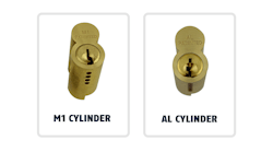
Photo 15 shows the sixth-pin conversion kit mentioned earlier. You would simply slide this little piece of brass over the housing in the cylinder and insert the spring and top pin to add that sixth pin for your assembly if that’s what you need. (Photo 16)
In photo 17, the lock is completely reassembled and put back together, following ABUS’ instructions. Now, the key lines up directly straight and can be removed when in the key retaining format. The lock is completely rekeyed to this key, 1-1-7-3-3, for a customer, ready to go.
Wayne Winton is the owner of Tri-County Locksmith Services, located in Glenwood Springs, Colorado. For more information, check out Wayne’slockshop.com and lockreference.com.
ABUS Step-By-Step Instructions
1. Unlock padlock.
2. Remove the #2 Phillips head screw in the shackle hole.
3. Remove cylinder from the padlock. Use the key to remove the cylinder after the screw is removed. It is important that the shackle is left in the open position at all times until the reassembly is finished.
4. For non-retaining, remove the Z-bar.
5. For key retaining, insert Z-bar on the end of the cylinder with the black dot facing up.
6. Reassemble padlock by replacing the cylinder. It is necessary to turn the cylinder to the open position when using the Z-bar. The cylinder should be flush with the base of the padlock body.
7. Re-install Phillips #2 head screw and tighten.
Wayne Winton
Wayne Winton is the owner of Tri-County Locksmith Services, located in Glenwood Springs, Colorado.


