Sargent Surface Vertical Rod Exit Device Provides Higher Level of Access Control
Over time, security needs change to meet the external and internal demands upon a facility. Changes can include upgrading to a higher level of access control or new locking mechanisms. Reasons for change can include complying with government regulations such as the Health Insurance Portability and Accountability Act (HIPAA), the 1996 federal law that restricts access to and requires protection for individuals' private medical information.
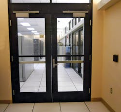
I was invited to observe the installation of a Sargent Surface Vertical Rod Exit Device with electrified trim onto the active leaf of a pair of doors located within an antechamber of a large facility. This pair of doors leads to a temperature and humidity controlled Information Technology (IT) Suite with offices. This is a mullion-free opening. The suite is built on a raised floor.
This non-fire rated pair of aluminum glass doors is equipped with concealed vertical rod exit devices. The right hand, active door for this non-astragal configured pair of double doors was equipped with electric latch retraction having remote release and a wall mounted badge reader. This exit device is being replaced with a Sargent Surface Vertical Top Rod Only Exit Device with electrified ETL trim; part number FGNB8774FETL32D. The electrified trim is configured for Fail Secure, requiring power to unlock.
A second pair of badge reader controlled doors lead from the corridor into the antechamber. This entry is equipped with a mortise lock exit device on the active door and concealed vertical rod exit device on the inactive door. The active door is equipped with an astragal. A door coordinator closes the inactive door before closing the active door. Within the antechamberare a sliding window and a receptionists' area that once controlled all access.
Access is controlled through both the corridor pair of doors and the antechamber pair of doors. Authorized badges must be presented to each door’s reader for access. Some personnel have authorization for access through both pairs of doors. Others have authorization through the corridor doors into the antechamber.
Note: All four of the doors are equipped with exit devices providing free egress at all times.
Why Surface Mounted?
A surface-mounted vertical top rod only exit device was chosen for several reasons. Since there is no mullion in this entry, each aluminum glass door must have its own latching mechanism to the doorframe header and or floor. Each door was equipped with concealed vertical rod exit devices that latched at the top and the bottom. The first reason was a change of exit device manufacturers. This means that the concealed latching mechanisms from Sargent Lock would not directly retrofit with the previous manufacturer's door prep.
The second reason since the fire rated corridor doors are under access control, there is no need for added expense of having both a top and bottom rod exit device leading from the antechamber.
The third reason is that by eliminating the bottom rod, the exit device cost of installation and operation will be more efficient for a longer period of time.
The aluminum glass door and jamb is equipped with a power transfer for the electric latch retraction. The existing cable was removed. New cable with 18 gauge two conductor was installed from the access control panel above the drop ceiling. The cable was run up the hinge stile across the top rail and down the latch stile into the electrified trim mounted onto the exterior of the door.
The Sargent 700 Series ET Control Trim for the surface vertical rod exit device cannot accommodate a mechanical lock cylinder. The decision was made to not install a key override such as a Sargent 306 Auxiliary Control on the active door or a lock cylinder equipped trim on the inactive door.
The new exit device was installed directly over the removed device mounting holes using the inactive door exit device as a guide. The device was ordered to size and fit without modification of the pushbar. New holes were drilled to accommodate the ET Control Trim, the center case and the mounting bracket. It is always important to measure the length needed for the top rod and the exit device is not always installed in the specified location.
To ensure a proper installation, a level was placed onto the rail prior to drilling the mounting bracket holes. All holes were drilled and tapped.
The exit device was mounted onto the antechamber door. The distance between the top case and the chassis assembly was measured. For this installation, the top rod had to be cut to length. Once the rod was cut, it was screwed into the top case and backed off about one and a half revolutions. Cutting the rod required a new hole for the rod adjustment pin. The hole was drilled in place and the pin installed.
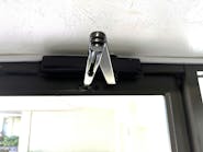
The rod guide provides protection against being bent or pulled out from the device. The rod guide base was positioned beneath the rod to set the location. Once placed behind the rod, it was slid to the halfway point between the device and the top case. Then we drilled and tapped the two holes for mounting the guide. The guide base was slid out from behind the rod and secured using the two mounting screws.
The location for the top strike was determined and marked using the latch as the guide. The four mounting holes were drilled and tapped. The top strike was installed. The mechanical operation of the exit device was tested to ensure proper operation. Adjustments were made as necessary.
To provide remote wireless release of the electrified trim, a BEA 433MHz Series digital transmitter and receiver were included in the installation. The inside range of this release is approximately 100-200 feet with minor obstructions. The 433MHz radio frequency signal can go through most walls.
The BEA 10RD433 receiver was installed in the wall behind the badge reader. The receiver operates on 24VDC. Since the wall separated the antechamber from the reception area, it would be able to receive the signal from the BEA one button transmitter, part number 10TD433HH. The transmitter is battery operated. The transmitter was programmed to the receiver.
The electronic operation of the exit device trim, badge reader, receiver and transmitter were tested to ensure proper operation. Now gaining access into the Information Technology Suite requires presenting an authorized badge and rotating the trim lever, the same procedure as gaining access through the corridor doors.
Important: Prior to purchasing and installing electromechanical access control devices, contact the Local Authority Having Jurisdiction (LAHJ) to insure the products to be installed meet their criterion.
FMI
For more information, visit your local locksmith distributor or:
- SARGENT Manufacturing Company, Telephone: 800-727-5477. Web: www.sargentlock.com/products/exit_devices.html
- BEA Inc., Telephone: 800-523-2462. Web: www.beainc.com/beainc/Downloads/Products/433MHz/75.5092_433.pdf


